
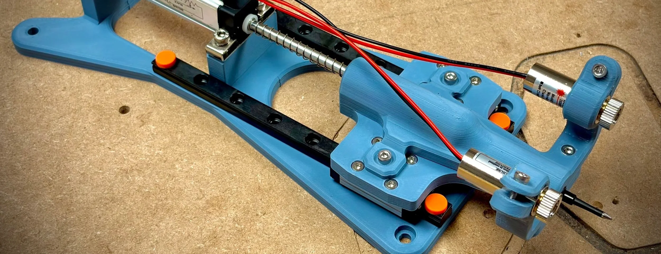
Machine tool testing device
2025-2026
Client: FlashCut CNC
Project evolution:
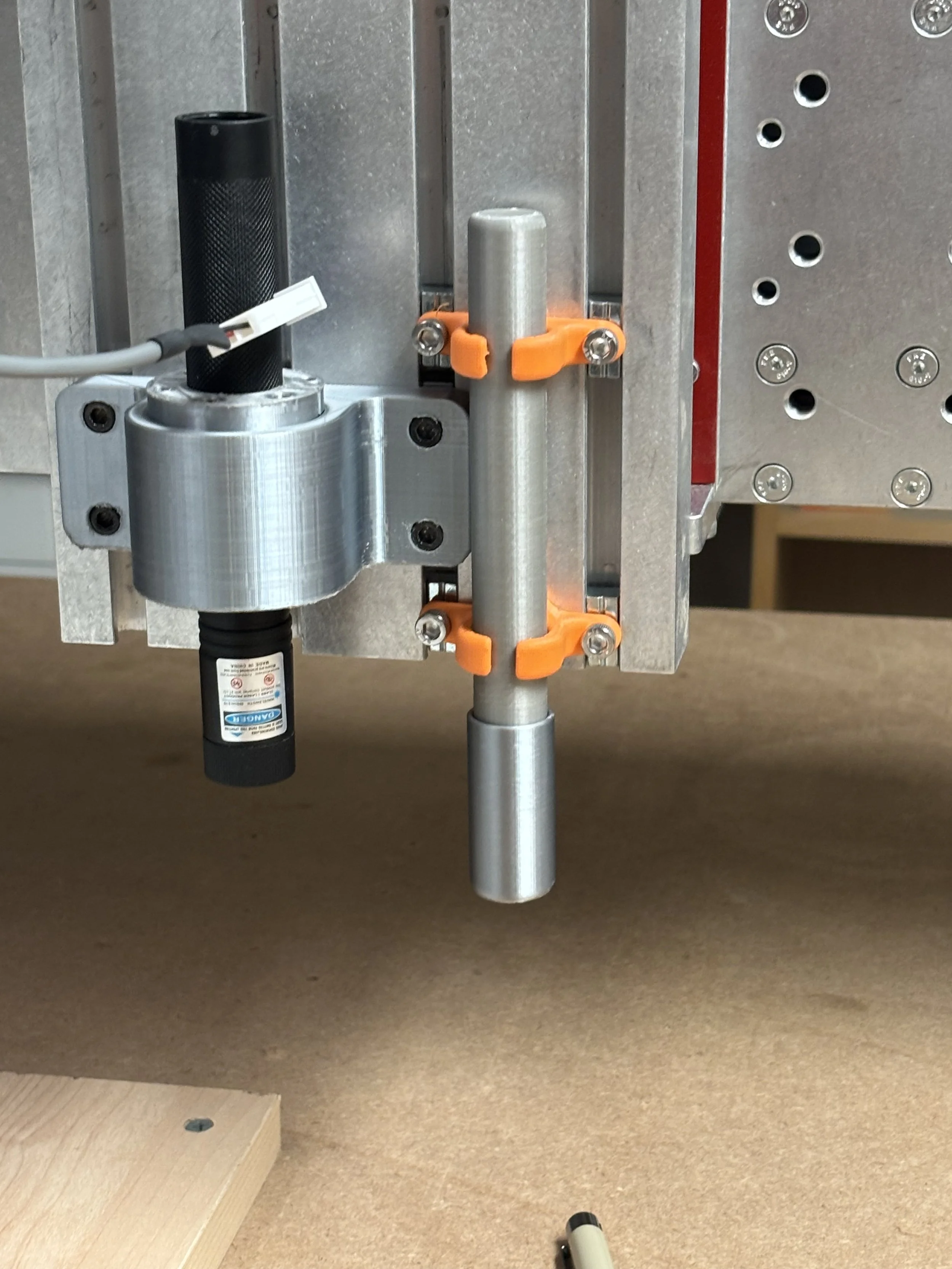
1
Original pen holder, laser mounted next to it.
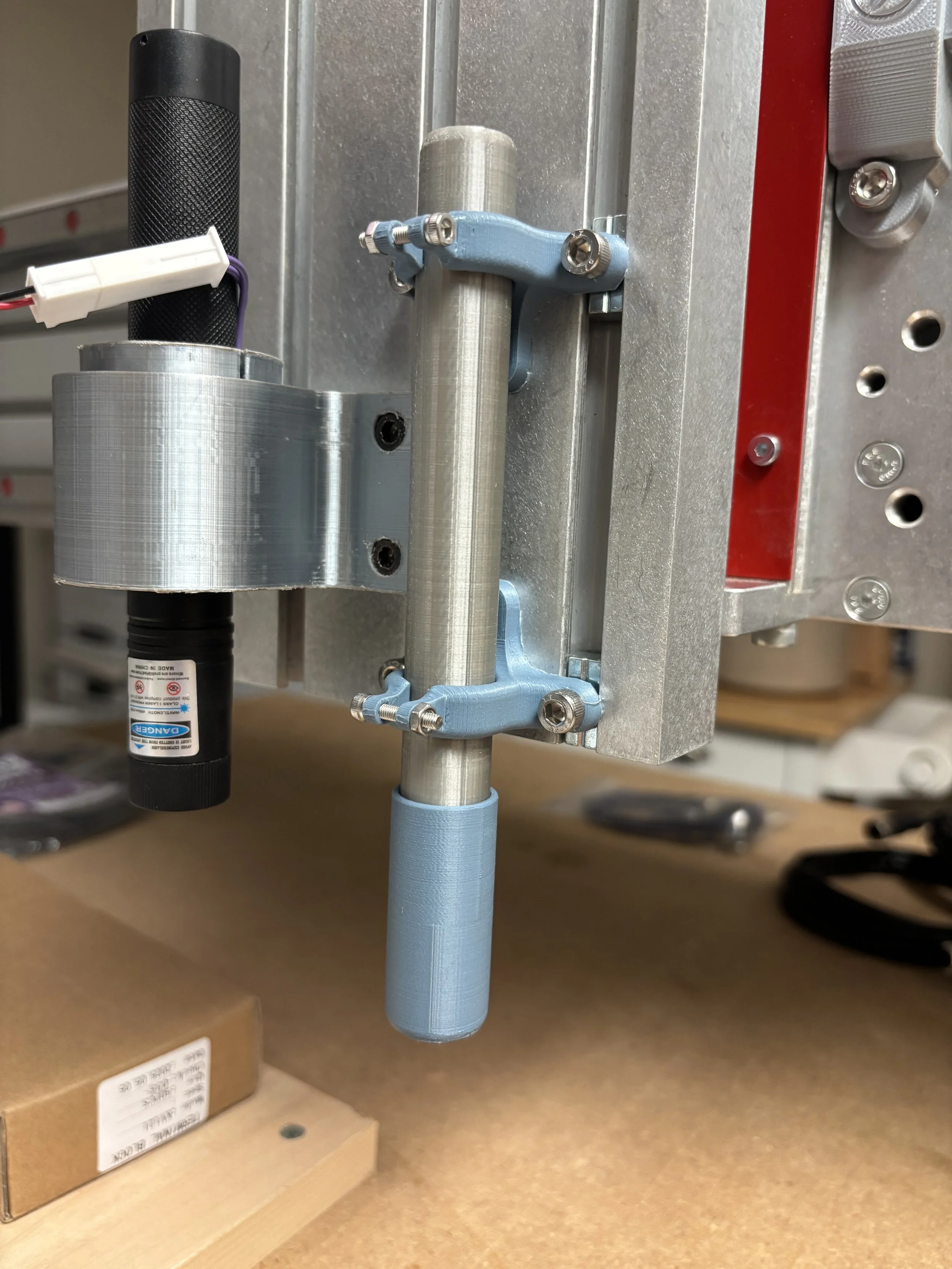
2
Updated pen holder design (more secure and stronger mount).
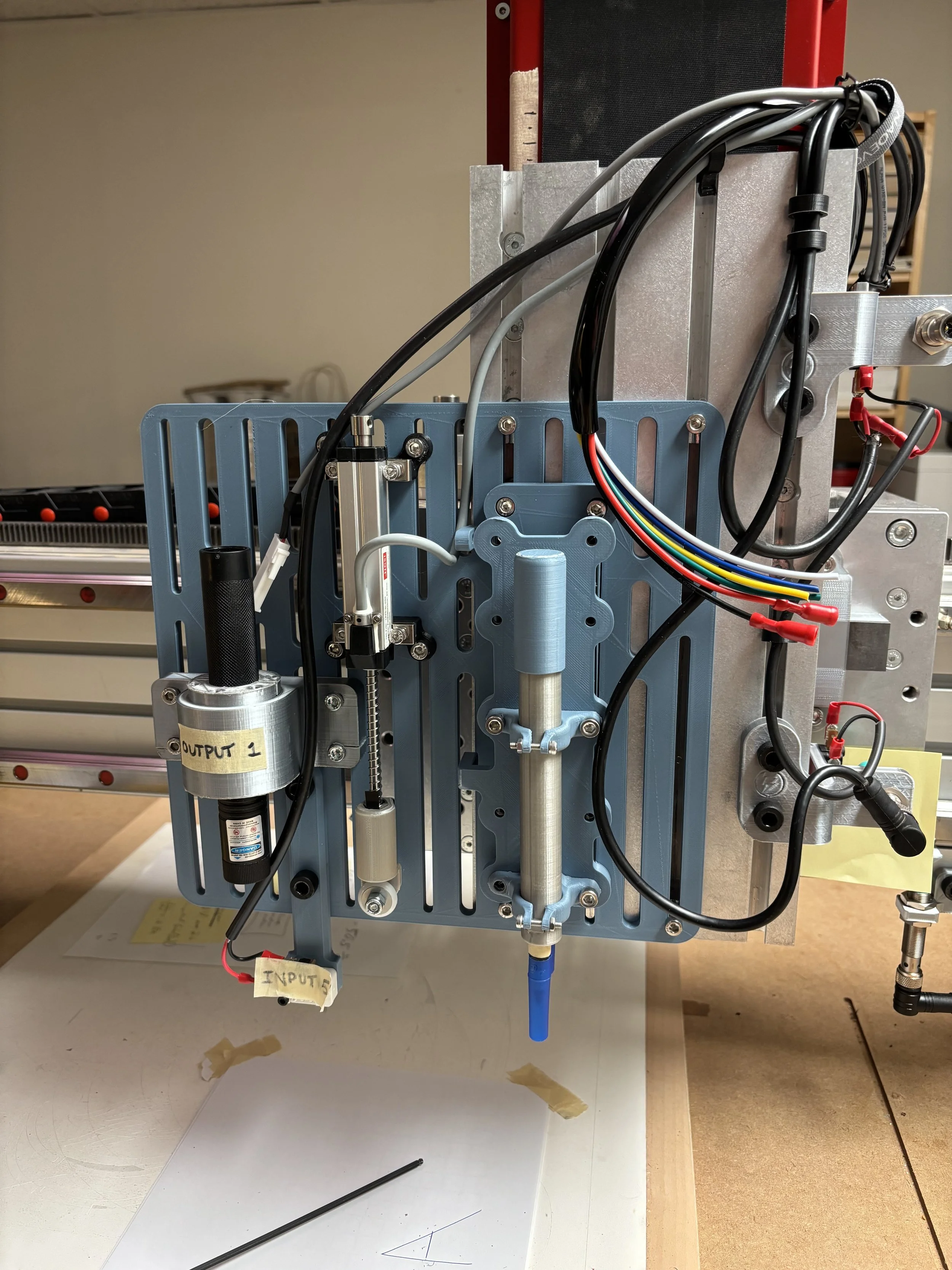
3
3D printed mounting panel with the laser, touch off, height control, and pen tool mounted.
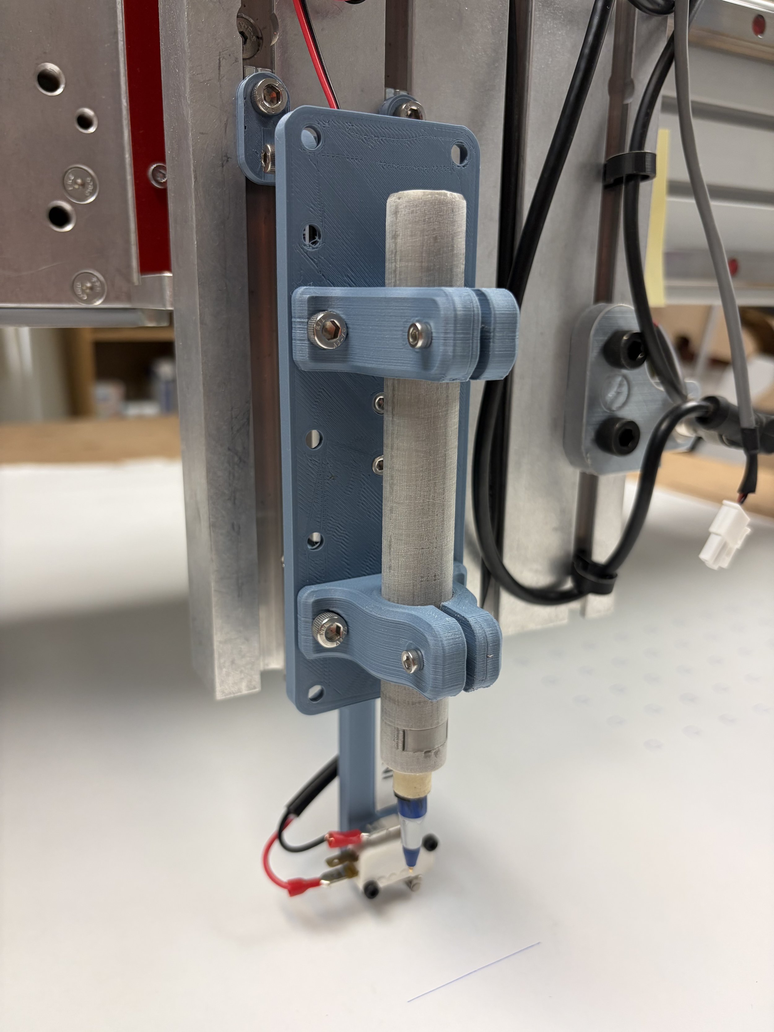
4
Linear actuator controlled pen tool combined with the touch off tool. laser and height control tools still separate.
Final solution:
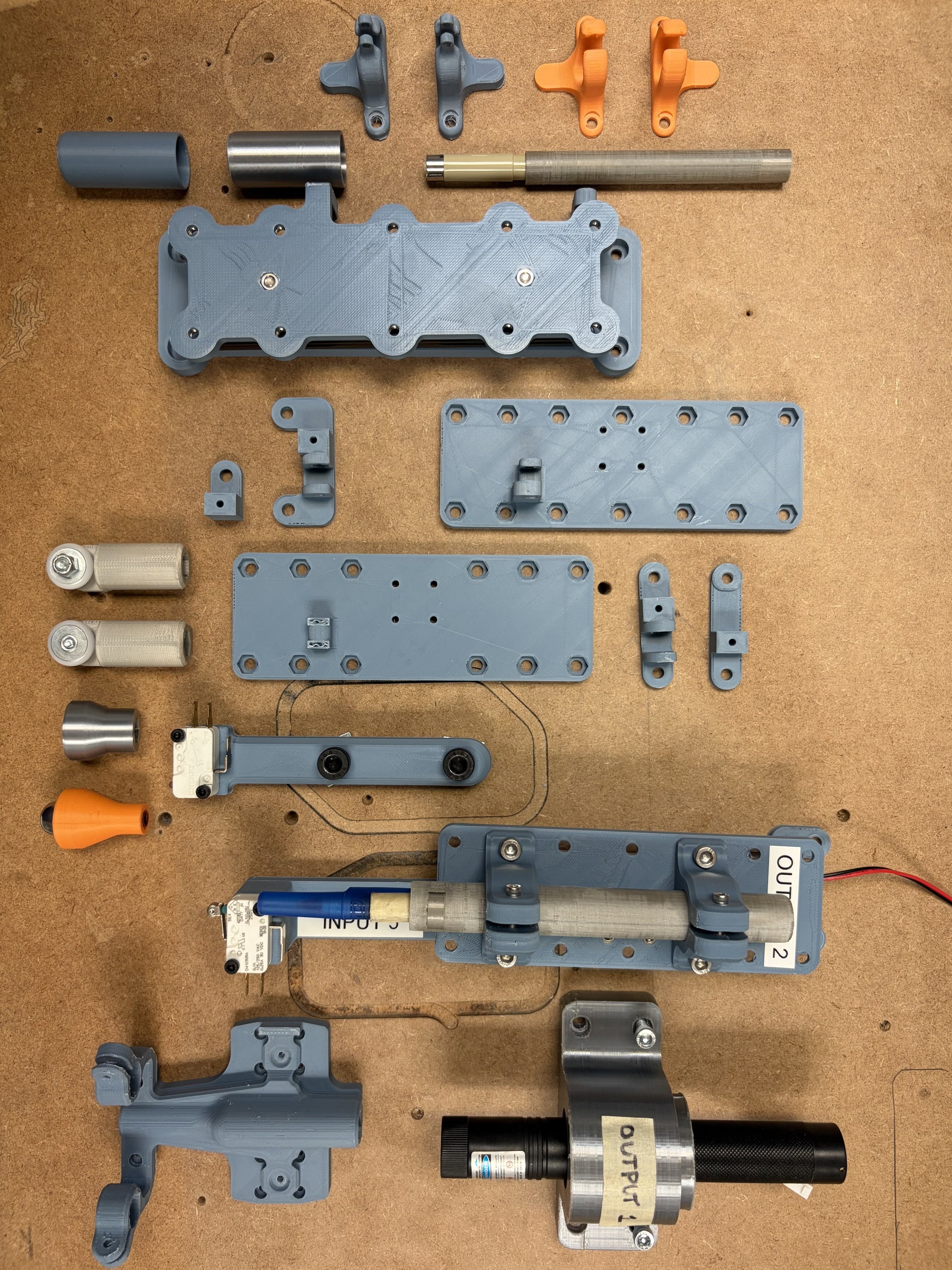
The “graveyard” of 3D printed prototypes. Each porotype was crucial for determining how the final design would work by combining their best features and fixing their issues.
Mounting plate
Inductive sensor
Laser 1
Pen
Create a single device to test/simulate different aspects of CNC laser and plasma cutting
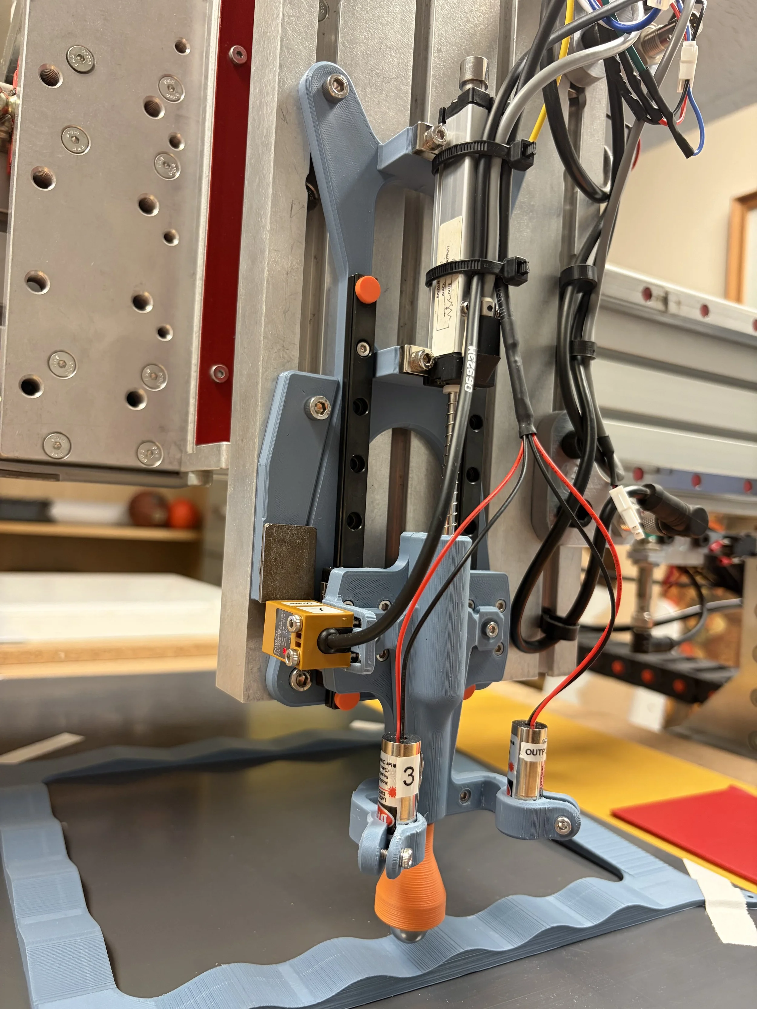
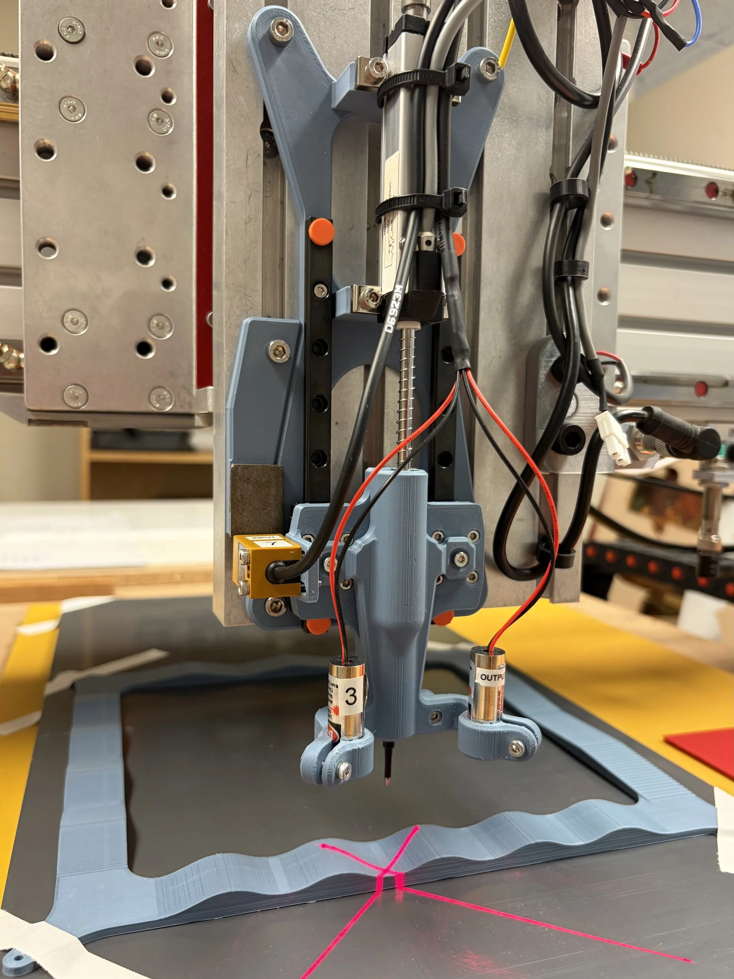
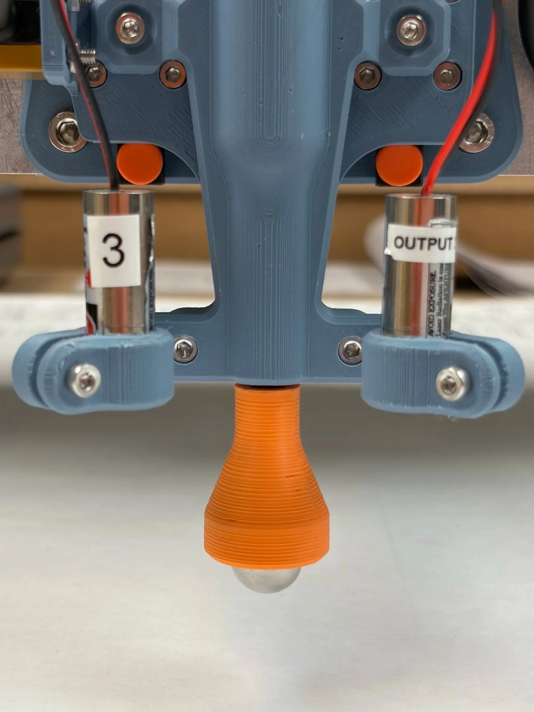
The final design successfully combines the touch off, heigh control, pen, and laser test tools into one device. By using linear rails, an inductive sensor, a linear potentiometer and two flat lasers, all testing can be done at once, while being more accurate than ever.
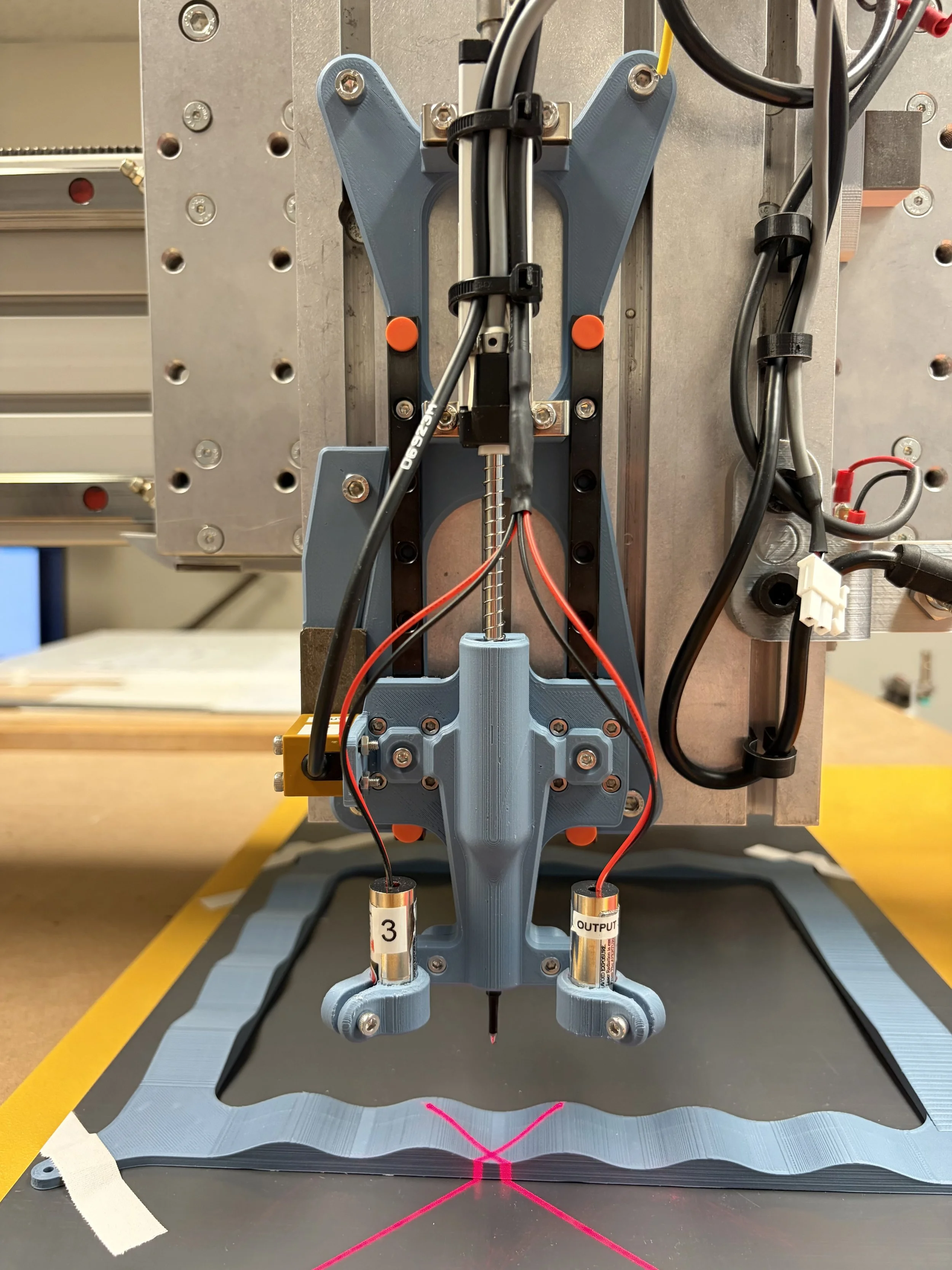
Linear potentiometer
Linear rails
Frictionless end cap/pen cap
Laser 2
Height control test track
Machine limit/homing/kill switch
2025-2026
Client: FlashCut CNC
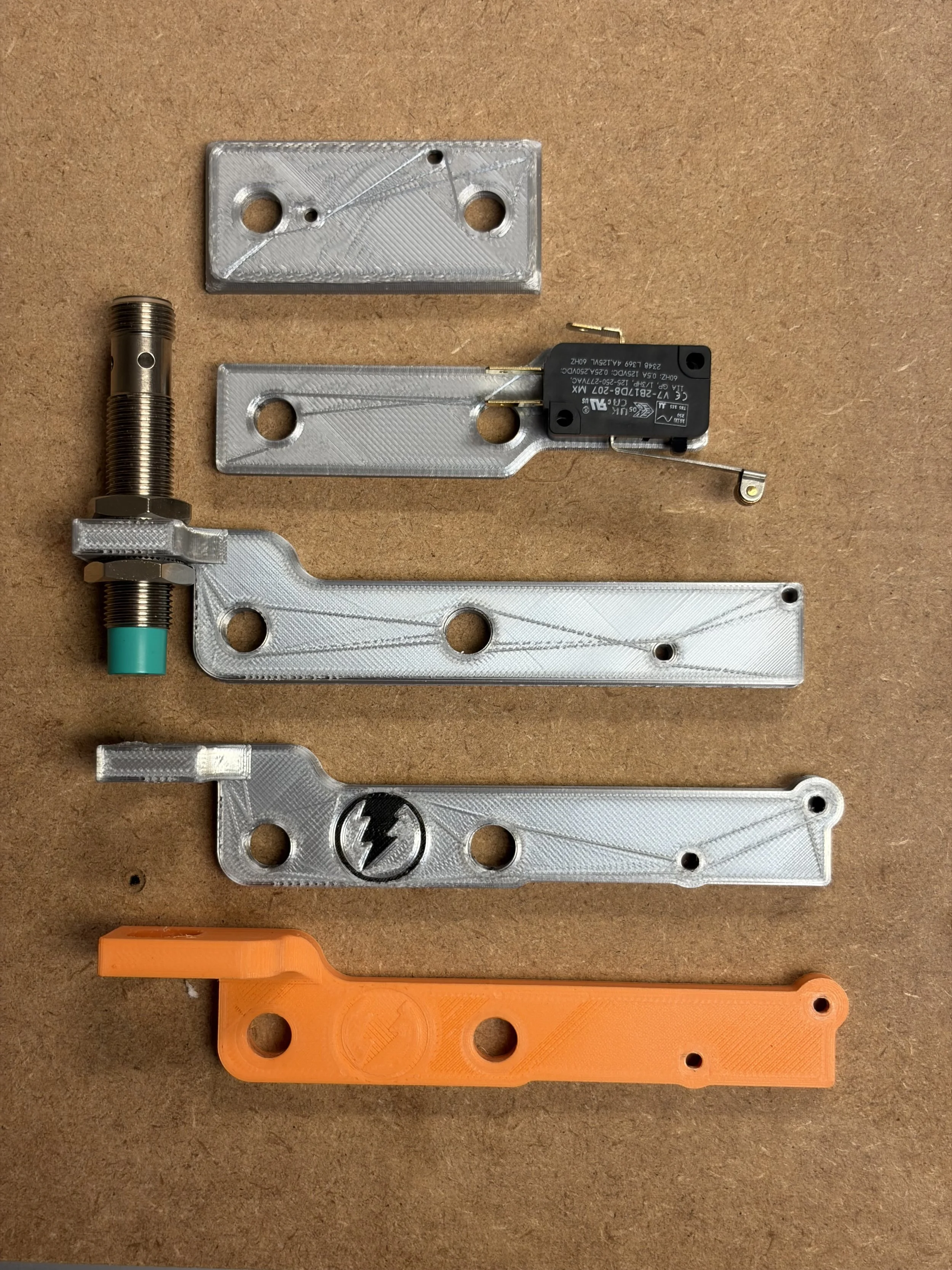
Prototypes:
Idea 1: The most basic attempt at mounting the kill switch
Idea 2: Working on getting the spacing correct for the screws while adjusting the height of the kill switch
Idea 3: first attempt at mounting the inductive home/limit sensor along with the kill switch
Idea 4: Refining the design and proportions
Idea 5: Attempts at increasing the strength of the inductive sensor mount
Final solution:
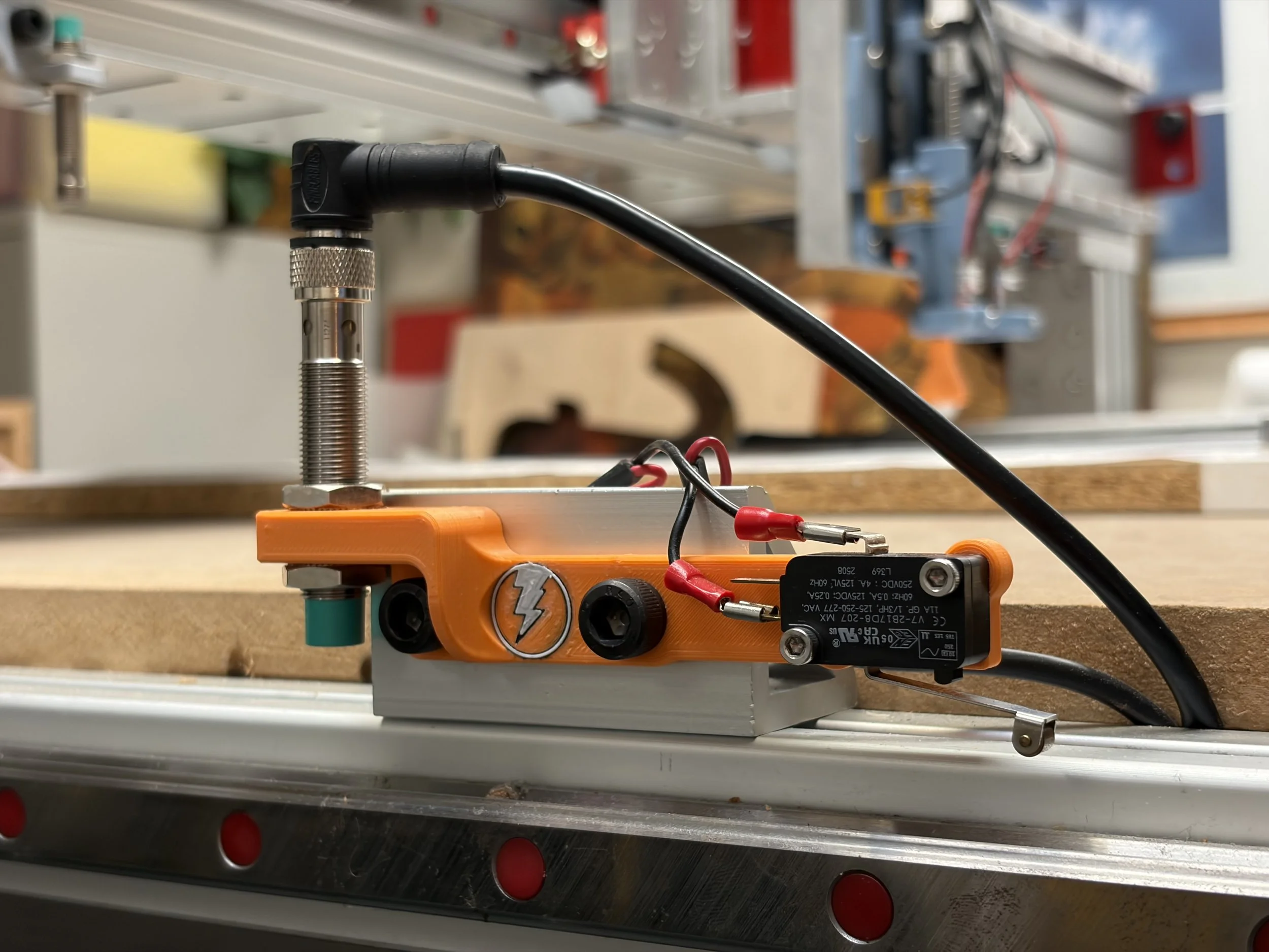
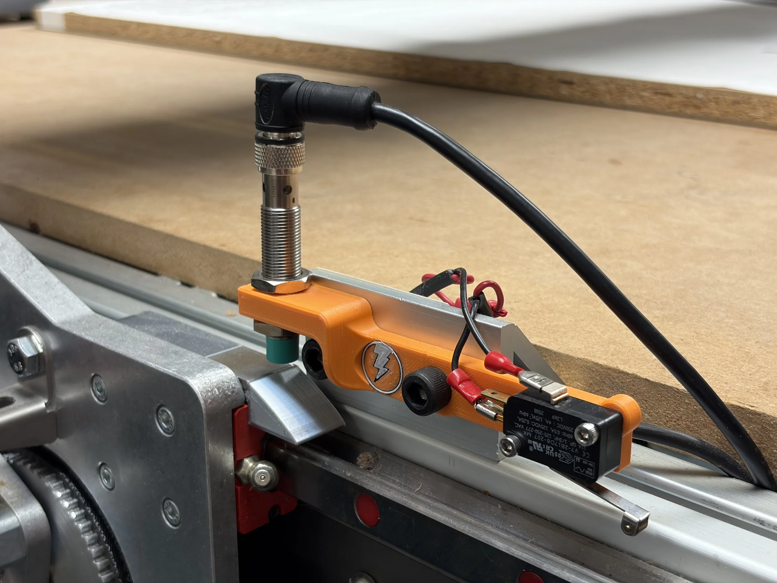
Stage 1: The two switches are securely mounted to the machine, waiting to be tripped
Stronger mount design
Inductive sensor
Create a safe and reliable mount for machine home/limit sensors
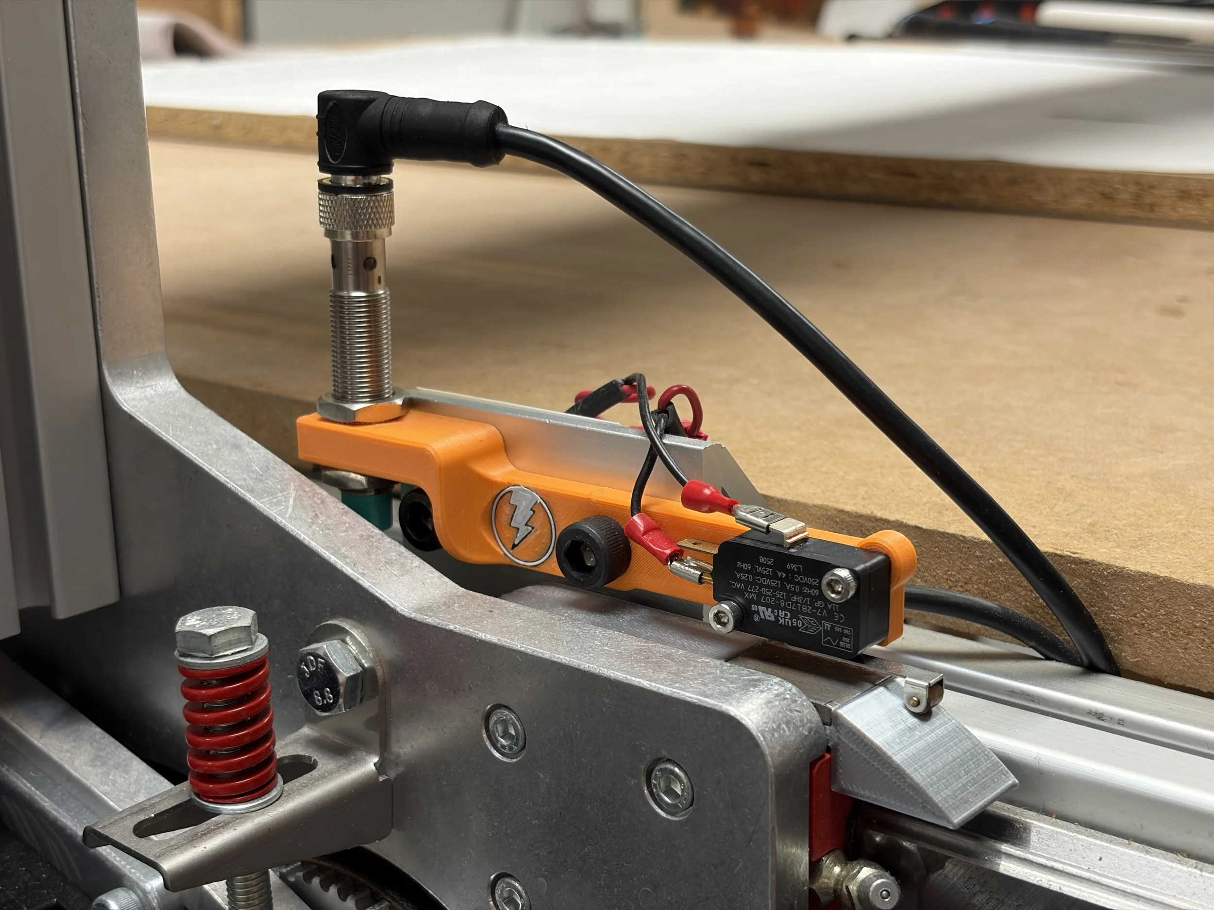
Stage 3: The limit switch failed to stop the machine! The machine continues to move until it trips the mechanical kill switch, instantly shutting off all power to the machine.
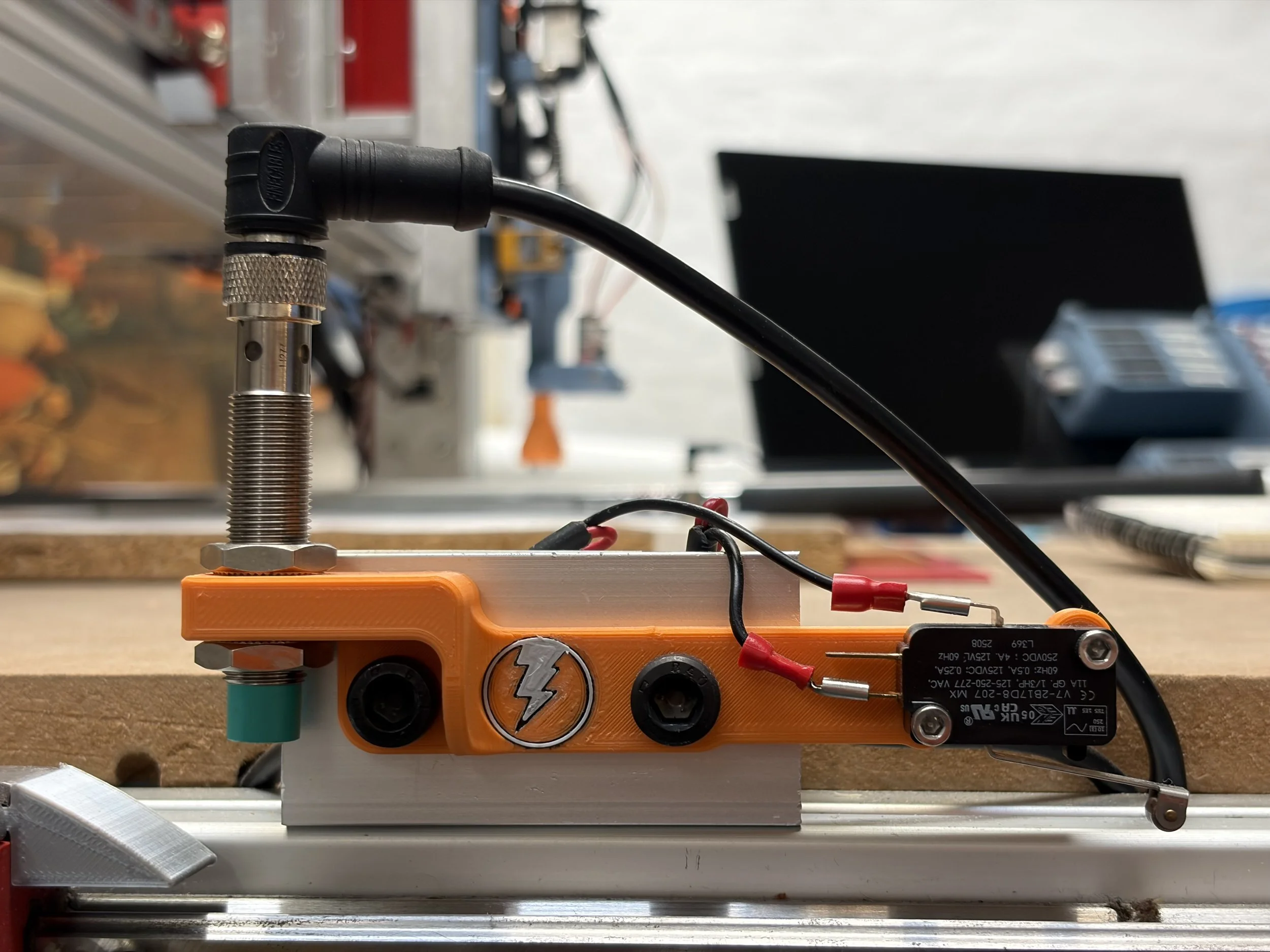
Roller lever switch
Stage 2: The machine has moved towards the home/limit sensor. A piece of metal trips the inductive sensor when it gets close.
Servo Motor Adapter
Fall 2024
Client: FlashCut CNC
Retrofit new servo motors onto a CNC router that previously used stepper motors.
After carefully measuring the motor and router mounting points I made some test 3D prints and finally a finished, solid 3D print that perfectly fit the existing and new mounting holes of the router and new servo motors


With the new servo motors mounted, I 3D printed a shaft coupler to connect the servo motor to the shaft of the Z axis. The holes seen on top of the coupler are for metal pins to be inserted to help strengthen the print and prevent it from sheering along the layers in the 3D print.


